 Federal Aviation Administration
Engine Halon Replacement
Nacelle Simulator
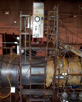
Beginning in 1995, work began on a simulator located at the FAA W. J. Hughes Technical Center. The project has spanned two project engineers and seen residence in two different structures on the facility. The simulator still remains under construction, but its current status is forever changing.
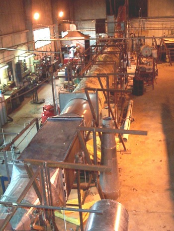
The nacelle simulator is a flow pathway having a front end to condition and supply air, a test section, and an exit to eject effluent from the entire device. The entire simulator is roughly 90 feet (27 m) long. The front end to the test section accounts for 50 feet (15 m), the test section approximately 20 feet (6.1 m), and the exit completes the balance of the length. The front end is composed of a supplying centrifugal blower, a heat exchanger, a stream straightener, and 32 feet (9.8 m) of 36-inch (91-cm) diameter duct. The test section consists of two concentric cylinders, having 24-inch (61-cm) and 48-inch (122-cm) diameters respectively. The annular volume of the compartment is approximately 100 cubic feet (2.8 m3). The test section also houses obstructions for clutter, equipment to support spray and residual fire scenarios, and hardware to deliver gaseous fire suppressants. The exit of the simulator consists of ducting to pass the effluent from the test section exit up and out of the building.
The front end of the test section contains hardware to provide air flow as prescribed in the MPSE. The air flow is provided by a centrifugal blower. Downstream from the blower, the flow then passes through a transition section and enters a heat exchanger housing. At this point, the flow departs the exchanger, passes through a grill structure, and finally enters a 36-inch (91-cm) diameter duct.
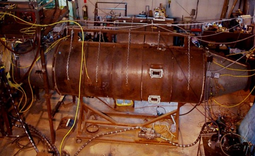
From this duct, the flow enters the test section; the heart of the simulator. This section contains hardware to provide a spray or residual fire scenario and receives the fire suppressant. The fire scenarios are located approximately 130 inches (330 cm) from the inlet of the test section. The spray fire scenario is located in the upper part of the annular cross section. A fuel delivery nozzle, a 2-inch (5.0-cm) tall baffle, electrodes to ignite the spraying fuel, and a local hot surface work integrally to provide the fire. In the lowest portion of the annular cross section lies a residual fire scenario. A pan with an ability to maintain constant fill level during a fire event, a 2-inch (5.0-cm) tall baffle, electrodes to ignite the pan contents, and a local hot surface combine to provide the residual fire threat. The last component in the test section to complete the simulation is the fire suppression system. The bottle storing the gaseous agent straddles the test section inlet diffuser. It is a unit on loan from the USAF, courtesy of the Aircraft Survivability group located at Wright Laboratories, Wright-Patterson AFB, Ohio. The unit is a right circular cylinder capable of varying volume and temperature control. The unit is plumbed into the test section roughly 36 inches (91 cm) from the inlet to test section. Currently, the agent is delivered into the test section through four 0.500-inch ( 1.3-cm) outside diameter tubes near the section wall penetrations. The agent is introduced in counter flow fashion within the test section.
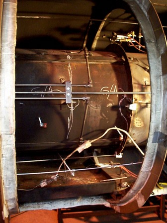
Gas concentration analysis is achieved by a Pacific Scientific HTL/Kin-Tech Halonyzer II, serial number 001. The configuration of the analyzer probes (sampling lines) within the nacelle simulator catches the concentration profile of the fire extinguisher discharge using all 12 channels. They are arranged in three rings, each having 4 probes apiece. Based on in-house configurations, the device capabilities and limitations follow :
- The analyzer can record gaseous agent distributions when mixed with air. These agents include the gaseous agents recommended by the IHRWG.
- Simultaneous 12 channel recording of the gas distribution profile to a resolution of 10 Hz.
- The analyzer can not be used during live fire testing.
Additional simulator process control, temperature, and pressure profiles are achieved with in-house computer/ analog-to-digital hardware and software.
For information contact:
Doug Ingerson